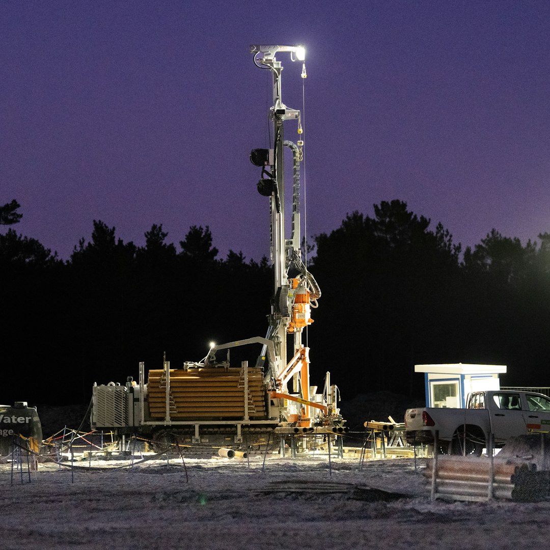

A rotating auger cuts into the ground and carries excavated material, known as spoil, to the surface. Once the shaft reaches its planned depth, it is checked before reinforcement and concrete are placed. This differs from driven piling, where a pile enters the ground by force and displaces surrounding soil. Neither method suits every site. Close boundaries, vibration-sensitive structures or buried services may favour bored pile drilling, while restricted access, slow penetration or temporary casing can affect the cost and programme. The design should reflect both investigation results and site limitations.
A pile transfers building loads through end bearing, shaft friction, or a combination of the two. End bearing acts at the tip when it reaches stronger soil or rock. Shaft friction develops along the sides as surrounding ground resists movement. Engineers use investigation information and structural requirements to select the diameter, depth, spacing and number of piles. A shaft that appears adequate near the surface may be unsuitable if soft layers continue below. Drilling records provide evidence of the material encountered, changes in depth and refusal, rather than leaving the final ground condition to assumption.
An open shaft must remain stable until the reinforcing cage and concrete are installed. Firm, dry ground may stand temporarily, but loose sand, fractured material and groundwater can cause collapse or contaminate the concrete. Steel liners or casings support the sides as drilling proceeds. They may be removed during concreting or left in place where the design and method require it. The crew must check alignment and ensure the casing does not obstruct the cage. Casing adds lifting, handling and sometimes extraction work, but it can reduce ground movement near services and neighbouring structures.
Rock changes the tooling and expected production rate. A standard soil auger may stop at competent rock, requiring a rock drilling tool or another method suited to the formation. Hard material can increase wear, spoil handling and noise, while irregular rock levels may mean that only some piles need specialist tooling. Hypothetically, an extension might have most shafts passing through fill while two encounter limestone. Confirming likely rock levels from available investigation information lets the contractor plan tools, access and spoil removal more realistically, instead of treating every pile as identical and allowing an unexpected obstruction to disrupt the programme.
Water entering a shaft can loosen surrounding soil, carry fines into the excavation or affect freshly placed concrete. Dewatering may control inflow, but pumping needs a suitable discharge route and consideration of nearby ground conditions. Casing may be preferable where continuous pumping is unsuitable. Equipment must also match the available working room. A compact rig could suit a rear block reached through a narrow side passage, whereas a larger industrial site may allow separate spoil-handling equipment. For specialist planning, foundation drilling services should be assessed alongside access, water control and the intended drilling sequence.
Before work starts, the team should check the pile layout, design depths, service information, access route, platform condition and concrete delivery sequence. The prepared platform must support and level the rig, since weakness can create safety and quality concerns. Each shaft should be logged by location, diameter, depth, material encountered, casing used and water conditions. Reinforcement cages need enough clearance to enter without catching on the sides, and concrete placement should avoid voids and weak zones. Comparing the drilling log with the planned profile gives the engineer a sound basis for responding to unexpected soil, rock or groundwater.